How far apart should solar street lights be placed? The honest answer depends on more than pole height or panel size. Road width, fixture optics, battery capacity, mounting height, weather, and required illumination all affect the spacing decision. A rural access road may need wider gaps than a busy pedestrian path. A narrow beam can leave dark strips between poles, even when the fixtures appear powerful.
James R. Benya, a respected lighting designer and author of outdoor lighting guidance, offers a useful principle: “Uniformity matters more than simply adding brightness.” That idea should guide every solar street-light layout. The goal is not to create isolated pools of intense light. It is to produce a continuous, comfortable route with acceptable visibility near crossings, entrances, bends, and drainage areas. Photometric software can test this pattern before installation. Field experience still matters.
In many projects, spacing may fall between 20 and 40 meters, but this range is only a starting point. Taller poles and wider beam angles can extend coverage. Trees, parked vehicles, hills, and seasonal shadows can reduce it. Small mistakes become obvious after sunset. A trial installation is often wiser than copying a supplier’s standard diagram. I would also avoid treating one spacing rule as universal. It can fail.
This guide explains how to evaluate pole height, light distribution, road conditions, battery autonomy, and local requirements. It also examines why measured illuminance and uniformity should support practical judgment. The right answer is the spacing that keeps people oriented, reduces dark gaps, and performs reliably through several cloudy nights.
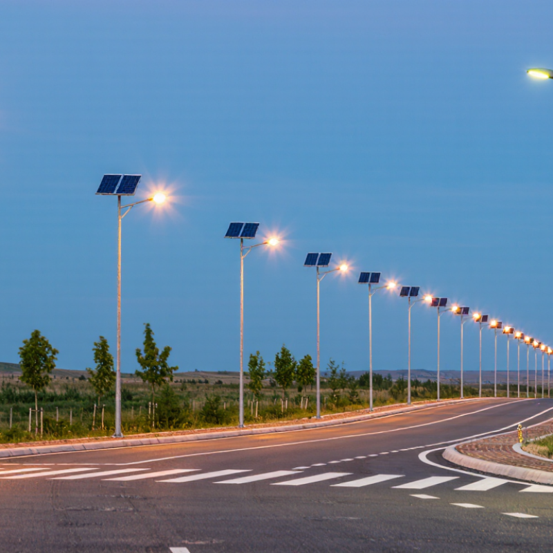
Solar street-light spacing should follow the roadway lighting class, not a pole-height rule of thumb. IES RP-8-22 groups motorized roads into M classes using factors such as traffic speed, road use, and pedestrian activity. Its maintained average pavement-luminance criteria range from 1.0 cd/m² for M1 to 0.2 cd/m² for M6. Higher-class roads therefore need more light on the pavement, but that does not automatically mean closer poles: optics, mounting height, road width, and uniformity all affect spacing.
Classify the road before estimating pole intervals. A low-speed residential street with few pedestrians may call for a different class than a busy arterial with frequent crossings. Then model the actual luminaire output, pole layout, pavement, and solar system’s expected operating conditions. IES RP-8 also evaluates uniformity and glare, so average brightness alone can hide dark gaps between poles. Check the adopted RP-8 edition and local design requirements; classification involves judgment, and borderline roads deserve a second review. A practical layout should include measured or verified photometric data, not just a spacing number from a product sheet. One missed detail can leave a crosswalk dim.
Start with the road, not the light. Measure the paved width, including shoulders that need illumination, and note bends, crossings, and trees. A narrow access lane needs a different layout from a broad road. Small details matter.
Pole height affects how widely light spreads. Taller poles can cover more ground, but spacing them too far apart may leave dark gaps between pools of light. For a first estimate, keep spacing around three to four times the mounting height, then check the lighting plan. For example, a 6-meter pole might suggest spacing of roughly 18 to 24 meters. That is only a starting point, not a rule. Road width, fixture optics, and obstructions can change the result.
Set a target illuminance for the road’s use, then review both average brightness and uniformity. A bright patch directly beneath each pole can still leave the road uneven. Ask for a photometric layout showing illuminance across the full road width, not just at pole locations. If possible, compare the plan with nighttime readings after installation. Solar output also changes with weather and season, so confirm the system can maintain its intended light level. One assumption may prove wrong; adjust spacing or aiming when the actual site shows a gap.
A 3–5:1 spacing-to-mounting-height ratio is a useful starting estimate for solar street lights. Measure spacing from pole to pole, and mounting height from the ground to the light fixture. For example, lights mounted 6 meters high would begin around 18–30 meters apart. That is only a start.
The lower end of the range usually deserves attention where people need more even light, such as narrow paths, entrances, or areas with frequent turns. Wider spacing may work on open, straight sections, but only if the fixture’s light distribution reaches between poles.
A broad roadway, tall trees, or uneven ground can change the result. Solar output also varies with system design and available sunlight, so spacing alone cannot guarantee a bright, uniform walkway.
Check the manufacturer’s photometric data, especially the beam pattern and recommended mounting height, before fixing pole locations. If possible, install a short trial section and inspect it after dark. Look for dark patches between poles and glare at eye level. I would not assume the first layout is perfect; even a small adjustment can improve coverage. Curves and intersections often need closer spacing than the straight sections beside them.
Solar street-light spacing should follow the actual beam pattern, not a fixed rule of thumb. A narrow distribution can leave dark gaps between poles, while a wide beam may create glare near homes or footpaths. Check the luminaire’s photometric data and compare its coverage at the planned mounting height. The spacing-to-height ratio is a useful starting point, not a guarantee.
Overlap matters. Adjacent light patterns should blend enough to avoid sharp dark bands, especially across crossings and bends. But excessive overlap can waste stored energy and make bright patches. Check at night. Walk the route and note changes in pavement brightness, not just whether each pole looks bright. Trees, road signs, utility cabinets, and parked delivery vehicles can block part of a beam. A layout that works on an empty road may not work in daily use. Move a pole or adjust its orientation where obstructions create persistent shadows. I would not trust the drawing alone; a small on-site trial can reveal flaws the plan misses. Recheck after installation, since actual aiming and surrounding objects may differ from the design.
Recommended pole spacing depends on mounting height, beam distribution, required overlap, and site obstructions. The chart uses a nominal 120° beam and a 25% overlap target. Beam footprint is calculated as 2 × mounting height × tan(beam angle ÷ 2); recommended spacing is 75% of the footprint.
Planning reference: At 6 m mounting height, a 120° beam produces an approximately 20.8 m theoretical footprint, supporting about 15.6 m pole spacing with 25% overlap. Increase overlap or reduce spacing where trees, buildings, curves, uneven terrain, or pedestrian-priority areas obstruct the beam.
How Far Apart Should Solar Street Lights Be Placed?
Verify Uniformity and Illuminance with Photometric Calculations
Spacing should come from measured light performance, not a fixed rule of thumb. Mounting height, road width, pole geometry, lamp distribution, and surface reflectance all affect the result. A practical starting point is a spacing-to-mounting-height ratio, but this ratio only guides the first layout. It cannot replace a photometric calculation.
Create a calculation grid across the carriageway, sidewalks, and conflict areas. Enter the luminaire’s verified photometric file, mounting height, tilt angle, and aiming direction. Then review average illuminance, minimum illuminance, and uniformity ratios. Check the darkest points between poles. A bright average can hide unsafe shadows. Small changes matter.
For example, poles placed 30 meters apart may perform well at eight meters high, yet fail when trees block part of the beam. I would test several layouts before approving construction. Include realistic conditions, such as a dusty lens, pavement aging, and moderate battery output. That assumption can be wrong.
Field measurements should follow installation. Use a calibrated illuminance meter at selected grid points after dark. Record weather, pavement condition, and operating time. Compare these readings with the model, then investigate large differences instead of ignoring them. Calculations are powerful, but they describe an expected installation, not every night on the road.
Pole spacing is a starting point, not a universal rule. Confirm each layout using the selected luminaire’s photometric file and the project’s applicable lighting criteria.
| Mounting Height | Pole Spacing | Spacing-to-Height Ratio | Average Roadway Illuminance | Minimum Illuminance | Uniformity Ratio (Emin/Eavg) |
Example Assessment |
|---|---|---|---|---|---|---|
| 6 m | 24 m | 4.0:1 | 10.0 lx | 3.0 lx | 0.30 | More uniform; suitable candidate for review |
| 6 m | 30 m | 5.0:1 | 8.0 lx | 1.8 lx | 0.23 | Check for dark areas between poles |
| 7 m | 28 m | 4.0:1 | 8.6 lx | 2.6 lx | 0.30 | Balanced candidate for review |
| 7 m | 35 m | 5.0:1 | 6.9 lx | 1.5 lx | 0.22 | Wider spacing may reduce uniformity |
| 8 m | 32 m | 4.0:1 | 7.5 lx | 2.3 lx | 0.31 | Balanced candidate for review |
| 8 m | 40 m | 5.0:1 | 6.0 lx | 1.3 lx | 0.22 | Verify minimum illuminance carefully |
Calculation basis: Illustrative values assume a 7 m-wide roadway, a generic 6,000 lm LED luminaire, single-sided pole placement, and a maintenance factor of 0.80. Average illuminance is estimated over the roadway area served by each pole; minimum illuminance and uniformity are representative point-by-point photometric results, not guaranteed product performance. Actual results depend on the luminaire’s IES/LDT file, optics, tilt, setbacks, pole arrangement, obstructions, and maintenance conditions. Check the applicable local lighting standard before selecting final spacing.
Use the actual beam pattern and mounting height. A fixed spacing rule is only a starting point. Check the darkest pavement areas between poles.
A higher pole usually spreads light across a wider area. However, the beam may become weaker at ground level. Test the planned height.
Include mounting height, road width, pole geometry, tilt, and aiming direction. Add the luminaire’s verified photometric file. Surface reflectance also matters.
Patterns should blend across crossings, bends, and walking paths. Too little overlap creates dark bands. Too much overlap creates bright patches and wastes stored energy.
Yes. Average brightness can hide very dark points. Review minimum illuminance and uniformity ratios. Measure between poles, not only beneath them.
Trees, road signs, cabinets, and parked delivery vehicles can block beams. An empty-road drawing may miss daily shadows. Move a pole or adjust its direction when needed.
Yes. Walk the route after dark. Compare pavement brightness along the entire path. Look for sudden changes.
Use a calibrated illuminance meter at selected grid points. Record weather, pavement condition, and operating time. Then compare readings with the calculation.
Yes. Consider a dusty lens, aging pavement, and moderate battery output. These conditions can reduce performance. That assumption may be wrong. Recheck it.
Determining how far apart should solar street lights be placed begins with classifying the roadway according to IES RP-8 criteria. The lighting class reflects factors such as traffic volume, pedestrian activity, road function, and surrounding conditions. Next, measure the road width and available mounting height, then identify the target illuminance and uniformity levels required for safe, consistent visibility.
As an initial planning estimate, use a spacing-to-mounting-height ratio of approximately 3:1 to 5:1. This ratio should be adjusted according to the fixture’s beam distribution, light output, pole arrangement, and the need for overlapping illumination. Trees, buildings, curves, intersections, and other obstructions may require shorter spacing or additional poles. Before installation, photometric calculations should verify average illuminance, minimum levels, glare control, and uniformity across the roadway. Field testing after installation can further confirm that the layout performs as intended.

Habel Lighting